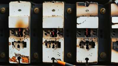
Choosing the right Power Switch is no longer a simple matter of comparing voltage and current ratings. Modern designs must balance efficiency, thermal behavior, switching speed, protection, cost, and reliability. A device that looks suitable on paper may still overheat beside a compact heatsink or create voltage spikes on a long circuit trace.
Industry demand makes this decision more important. The International Energy Agency reported that global electric car sales exceeded 14 million in 2023, representing about 18% of new car sales. Its Renewables 2024 report also recorded nearly 510 GW of renewable capacity additions in 2023. These systems depend on efficient switching across inverters, chargers, motor drives, and energy-storage equipment. Every percentage point of lost efficiency becomes heat, wasted energy, or reduced operating time.
Alex Lidow, co-founder and CEO of Efficient Power Conversion, has described power electronics as “the technology that enables the efficient conversion of electrical energy.” That principle applies directly to switch selection. Silicon MOSFETs may remain practical for many low-cost applications. SiC MOSFETs can offer lower losses at higher voltage. GaN devices may provide fast switching in compact power supplies, but layout sensitivity and gate-drive requirements deserve careful attention.
There is no perfect switch.
Engineers sometimes trust headline specifications too quickly. I have seen designs focus on low RDS(on), then underestimate gate charge, thermal resistance, or electromagnetic interference. The better choice begins with the real load profile, switching frequency, cooling path, fault conditions, and safety margin. This guide explains how to evaluate those details with evidence, not marketing language alone.

Start by defining what the power switch must control. Record the load voltage, normal current, peak current, and switching frequency. A motor, heater, lamp, and digital circuit behave differently. Motors can create high inrush currents during startup. Inductive loads may also produce voltage spikes when switched off. Measure these conditions when possible. Estimates can be misleading.
Operating conditions deserve equal attention. Check the minimum and maximum supply voltage, ambient temperature, humidity, vibration, and available enclosure space. A switch used inside a warm cabinet may need more current capacity than laboratory testing suggests. Allow practical safety margins for continuous operation. Do not size from the nominal rating alone. Fault conditions matter too. Consider short circuits, stalled motors, repeated switching, and accidental overloads.
Review the technical datasheet carefully. Confirm contact or channel ratings, isolation requirements, leakage current, response time, and thermal performance. For higher-power designs, examine heat dissipation at the actual load, not just the advertised maximum. In my experience, a small temperature rise can become significant after hours of operation. Bench tests should include cold starts and extended cycles. This is where weaknesses often appear. I have also seen designs pass a short test but fail after repeated switching. That result deserves investigation, not excuses. A qualified engineer should verify the selected switch against applicable electrical safety requirements and the equipment’s documented operating limits.
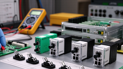
Choosing a power switch starts with the load, not the package label. In field testing, I check voltage, continuous current, inrush current, and switching frequency before comparing devices. Mechanical switches use physical contacts, offering simple isolation and a clear tactile response. They can handle many passive loads, but contact bounce creates brief electrical noise. That detail matters. For lamps or low-speed controls, it may be acceptable.
Solid-state switches use semiconductors instead of moving contacts. MOSFET-based switches usually suit fast DC switching, low voltage drop, and quiet operation. Bipolar transistor switches can be economical, yet they may need more drive current. For AC loads, triac-based switching can work well, especially with resistive heaters. However, leakage current and heat must be checked at the real load, not only at room temperature. I once underestimated inrush from a small motor. The switch survived briefly, but the enclosure became uncomfortably warm. That was not a good design margin.
Switching method also changes performance. Manual control is direct and easy to diagnose. Relay control provides electrical separation, while transistor control enables rapid, repeated operation. Pulse-width modulation adjusts average power, but it can create electromagnetic interference and audible noise. Zero-cross AC switching reduces some interference, although it is less suitable for phase-control applications. Check datasheets for derating curves, isolation ratings, fault protection, and required heat sinking. A bench test with the actual cable, load, and ambient temperature reveals weaknesses that calculations can miss. I would also leave more margin than my first estimate suggests.
How to Choose the Right Power Switch for Your Needs?
Evaluate Voltage, Current, and Load Compatibility
Choosing a power switch starts with the actual electrical conditions, not the label on the equipment. Check the system’s maximum voltage, including startup spikes and switching transients. A switch rated for 12 volts DC may not safely control 12 volts AC. The current rating also needs careful attention. Measure the normal operating current, then allow extra capacity for temperature, wiring losses, and brief surges.
Load type matters just as much. Resistive loads, such as heaters, are relatively predictable. Motors, solenoids, and transformers create inrush current when energized. Their running current may look harmless, while startup current quickly stresses the contacts. For these loads, select a switch with suitable AC or DC ratings and confirm its inductive-load specifications. Never assume a general current rating covers every application.
In field testing, I inspect the datasheet, measure the real load, and check the switch after repeated cycles. Warm terminals, pitting contacts, or a faint burning smell indicate trouble. Keep it cool. I once selected a switch based only on steady current and ignored startup demand. It worked briefly, then failed. That mistake reinforced a useful habit: compare voltage, continuous current, peak current, load category, and operating temperature together. If the figures are uncertain, testing under the worst expected condition is safer than trusting an optimistic estimate.
Evaluate the switch's rated voltage, continuous current, and compatibility with the load type before selecting a component.
The chart shows representative maximum ratings commonly found in non-branded switch categories. Voltage and current ratings must be checked independently, and AC ratings should not be applied to DC circuits without confirmation. Motors, solenoids, lamps, and other inductive or inrush loads may require derating, arc suppression, or a relay/contactor.
Choosing the right power switch starts with safety, not appearance. Check its voltage and current ratings against your equipment’s real operating load. A switch should handle startup surges without overheating. Look for insulation, grounding provisions, and protection against accidental contact. Clear switching positions also reduce mistakes during maintenance. Small details matter.
Durability depends on construction and use. A switch in a workshop may face dust, vibration, oil, or repeated operation each day. Choose a housing suited to those conditions, with strong terminals and a reliable actuator. Environmental protection ratings can indicate resistance to moisture and particles, but they do not make installation careless-proof. Confirm the rating for the exact location, including outdoor exposure, condensation, and temperature changes. I have seen suitable switches fail because water entered through an unsealed cable opening. The switch was not the only problem.
Tips: Measure the load instead of guessing. Leave a safety margin above normal current. Inspect terminals after installation. Test the switch under realistic conditions, not only on a clean workbench. If the environment is harsh, review the choice with a qualified electrical professional. A higher rating is not always better; compatibility, enclosure design, and correct installation still decide performance. Reflect on the weakest point in the system. It may be the cable, mounting surface, or protective cover.
| Switch Type | Typical Electrical Rating | Recommended Application | Key Safety Features | Typical Mechanical Life | Environmental Protection | Typical Operating Temperature | Relevant Evaluation Standard |
|---|---|---|---|---|---|---|---|
| Rocker Switch | Up to approximately 10 A at 250 VAC for common appliance-style versions | Indoor equipment, power strips, appliances, and control panels | Insulated actuator, clear ON/OFF indication, optional double-pole switching, finger-safe terminals | Approximately 10,000–20,000 operations, depending on load and construction | Common versions: IP40; sealed versions may reach IP65 when correctly installed | Typically −20°C to +85°C | IEC 61058-1 for appliance switches; IEC 60529 for IP rating |
| Toggle Switch | Common panel versions range from 5 A to 15 A at 125/250 VAC | Industrial controls, vehicles, machinery, and exposed operator panels | Positive mechanical action, protective boot option, maintained or momentary switching, double-pole option | Approximately 10,000–50,000 operations; sealed designs generally provide better contamination resistance | Standard versions may be IP40; sealed panel versions can reach IP67 with a suitable seal and installation | Typically −40°C to +85°C | IEC 61058-1 or IEC 60947-5-1, depending on the application |
| Pushbutton Switch | Typically 1–5 A at 125/250 VAC for compact control versions | Start/stop controls, instrumentation, control panels, and user interfaces | Momentary or latching action, guarded actuator options, contact blocks with normally open or normally closed circuits | Approximately 50,000–100,000 operations for industrial control versions | Unsealed versions commonly IP40; sealed versions may provide IP65 protection from dust and water jets | Typically −20°C to +70°C | IEC 60947-5-1 for control circuit devices; IEC 60529 for enclosure protection |
| Rotary Selector Switch | Usually 2–5 A at 250 VAC for multi-position control circuits | Mode selection, voltage selection, fan-speed control, and multi-position equipment settings | Detented positions, tactile position feedback, removable keys on some versions, and contact separation between settings | Approximately 10,000–30,000 operations | Typical panel versions are IP40–IP54; higher protection requires a sealed design and suitable panel gasket | Typically −20°C to +70°C | IEC 60947-5-1 and IEC 60529 |
| Emergency-Stop Pushbutton | Common contact blocks are rated up to approximately 10 A at 240 VAC, subject to the exact configuration | Machinery and systems requiring rapid removal of hazardous motion or energy | Red actuator with contrasting background, latching action, twist or pull-to-reset, normally closed safety contacts, and positive opening action | Often rated for at least 100,000 mechanical operations; safety performance depends on the complete control system | Common panel versions are IP65 or higher when fitted with the specified sealing accessories | Typically −25°C to +70°C | IEC 60947-5-1, ISO 13850, and ISO 13849-1 for applicable machine safety functions |
| Disconnect or Isolator Switch | Common industrial ranges include 16–63 A at low-voltage AC ratings | Main isolation, maintenance access, motor circuits, and equipment power entry | Visible or clearly marked OFF position, lockable handle, adequate contact separation, and multi-pole isolation | Typically 10,000–20,000 mechanical operations for enclosed isolator designs | Enclosed versions commonly range from IP65 to IP66 for dust and water-jet protection | Typically −25°C to +60°C | IEC 60947-3 and IEC 60529 |
Select the Best Switch Based on Installation and Maintenance Needs
Installation conditions should guide your power switch choice. Measure the available panel space before ordering. A compact switch may fit tightly, but poor clearance can complicate wiring and inspection. Check the circuit voltage, current, load type, and switching frequency. Motors and heating equipment may require stronger contact ratings than lighting circuits. Moisture, dust, vibration, and outdoor exposure also affect enclosure selection. A qualified electrician should verify compatibility with local electrical requirements.
Think about maintenance before installation. A switch with clear terminals and accessible mounting points usually saves service time. Leave enough room for safe testing and wire replacement. Label each circuit clearly, especially in crowded control panels. For outdoor equipment, inspect seals and cable entries regularly. Loose connections can create heat, discoloration, or intermittent operation. Small warning signs matter.
I once underestimated access space during a repair. The switch worked, but testing it was awkward and slow. That experience changed my selection process. Now, I consider gloves, tools, lighting, and future repairs. Not every installation needs the most expensive option. However, choosing only by purchase price can create hidden labor costs. Review the manufacturer’s technical data, confirm the operating environment, and record inspection intervals. A simple maintenance log can reveal repeated faults before they become serious.